MTE-6500
An integrated smart production line for aluminum doors and windows
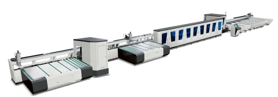
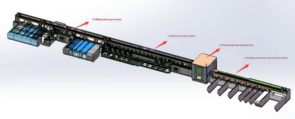
The production line is mainly composed of the following parts: (toping of materials at the right end of the equipment, left end of the output)
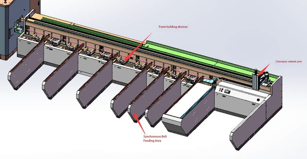
Part 1 : Synchronous belt feeding and robot transfer
The synchronous load cache area is mainly used to store profiles to be cut, and can store 6-8 profiles at the same time; The caching area can be set up so that workers can concentrate on loading to minimize the frequency of workers’ loading.
The robotic delivery part mainly consists of the robot closing the rough profiles to the cutting machine at any angle for cutting of a corresponding length.
Part 1 : arbitrary angle cutting host part
The arbitrary angle cutting mainly completes the severing of the rough mold, and can cut the mold at any angle between ± 45 °.
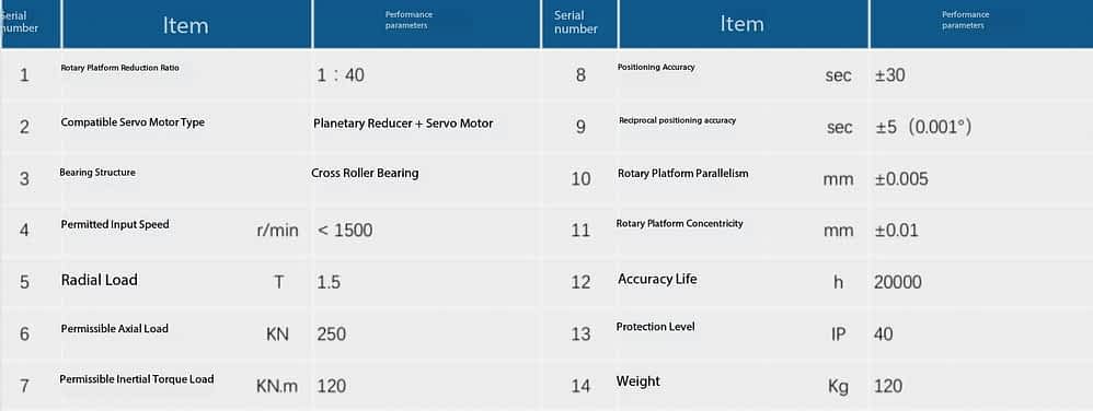
The rotary structure of the arbitrary angle cutting machine adopts PT series roller hollow rotary platform。 The platform is made of ring-shaped envelop, cam input and shaft output, which can achieve high precision and high load, high speed and no vibration, smooth and no noise .
Part 1 : Drilling and Milling Section
This section consists mainly of the following workplaces: the right rear drilling mill position and the left rear dipstick position; A permanent hole drilling position; Connected hole drilling position (with laser drawing capability); The traction robotic part; The pallet rolls and the tightening part of the mold.
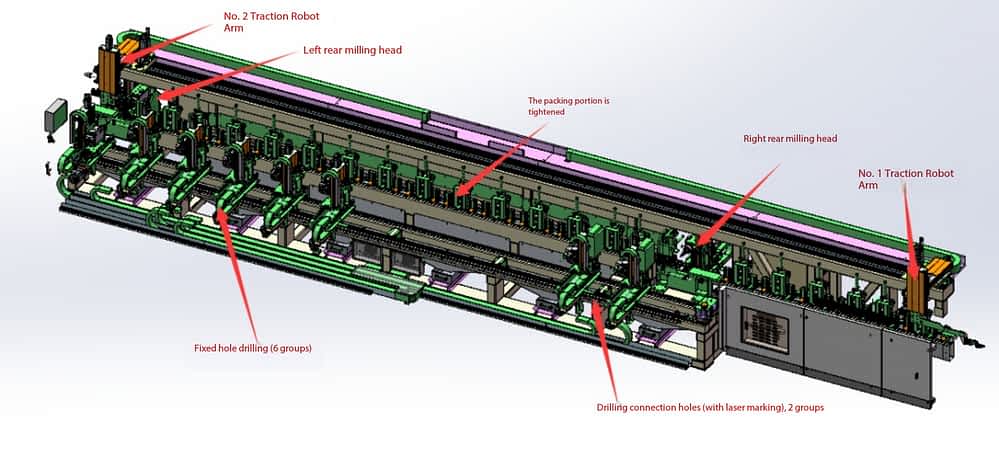
Right rear drilling milling head work position: can be processed frame profile right end of the injection hole and corner code screw hole (or pin hole); A filler hole and a horn-code screw hole (or screw hole) at the right end of a medium-hung type;The right end of the fan profile is filled with glue hole, corner code screw hole (or pin hole), milling drive bar sharp corner and milling guard angle.
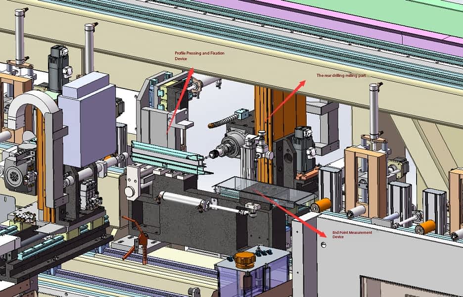
Because the angle-code screw hole (or stud hole) face tolerance requirements are relatively high, in order to avoid the compound errors in the cutting length of the mold and the position errors of secondary positioning causing the combined error of the machining face to be too large and affecting the assembly quality of doors and windows, In this workplace, a relative position measurement mechanism for the welded end has been added, and the measurement mechanism feeds the actual measurement data back to the control system, which compensates the actual position with the corresponding algorithm, so that the weld tolerance of the machining can steadily meet the assembly requirements.
l Left rear drilling milling head work position : This work position is arranged symmetrically with the right rear drilling work position to complete the machining of the left end of the profile .
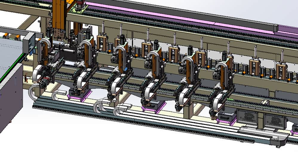
l Fixed hole drilling machine position: This part is equipped with six drilling and milling machine heads, which can process six frame installation holes at the same time, and can also process more than six installation holes。 The minimum aperture of the installation hole is 280 mm. The six sets of heads are positioned in the corresponding position according to the data sent by the control system, and porous machining at the same time improves efficiency.Each machine head is equipped with a clamping cylinder to position and clamp the profile.
l Connection hole drilling machine position (with laser marking): equipped with two sets of drilling and milling machine heads (with laser marking), can simultaneously process 2 frames on the mullion screw connection hole or laser marking mullion positioning line (one side or two sides optional), can also process multiple sets of hole position (or marking); The user can choose drilling or marking according to the corresponding door and window technology.
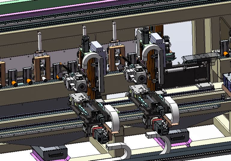
Traction Manipulator Part: This part is equipped with two sets of traction manipulators. The 1 # traction manipulator pulls the cut profile to the connection hole drilling station, and the right end of the profile is positioned. After the right workbench clamping and fixing device is fixed, the 1 # traction manipulator runs to the sawing clamping position。 2 # The traction machine takes the mold from the joined hole drilling position to the fixed hole drilling site, locates the mold at the left end of the mold, and tightens the fixture from the left workbench to fix the mold. 2 # The pull machine returns to the preparation position.The profile processing is completed in sequence.
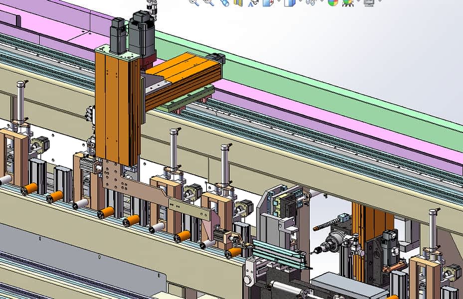
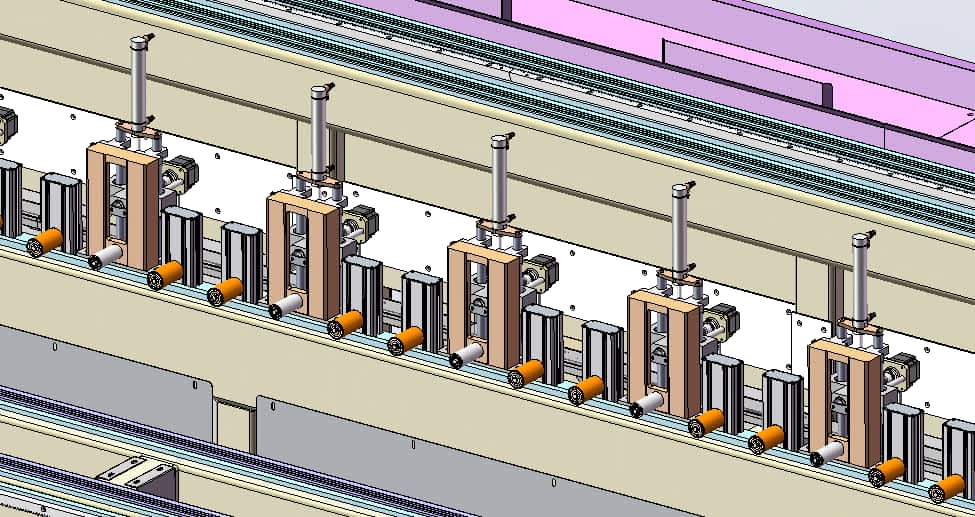
l Support roller and profile clamping part: when the profile is transported by the traction manipulator, the support roller and the profile piece are rolling friction to minimize the profile traction resistance and avoid the profile scratching during the profile transportation, and to improve the processing quality of the profile。The extension of the vertical clamping part of the clamping rod is completed by a trapezoidal screw driven by a stepping motor controlled by the system. Because of the numerical control, the system can determine the length of the extension of the clamping rod according to the relevant cross-sectional information of the processed profile, so as to adapt to the processing of different cross-sectional profiles.
The tray extrusion tightening part is arranged in three areas: six sets of fixed profiles to be cut are arranged before the right milling head; There are 14 groups arranged between the left and right millheads, and the pallet tightening device under system control only tightens within the length range of the mold, and does not move outside the length area.
Part 4: Milling the finished material
The milling feeding part consists of the following workplaces: First feeding table (right); Print the labeled workspace instantly; Four-axis drilling and milling position; Second loading platform (left); Towing a robotic hand; The pallet rack unit.
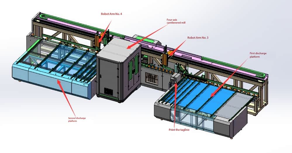
l The first discharging table: The 3 # manipulator pulls the profile to the first discharging table, and the left end is positioned. After the clamping device clamps the profile, the 3 # manipulator returns to the ready position. At the same time, the printer prints the label and attaches it to the profile。 If the current profile has no elements to be processed, it is discharged from the first discharge station.
L Printing and labeling section: Located on the left side of the first discharge table。The relevant information of each profile is printed on the self-adhesive label, and the label is automatically attached to the profile surface (the label is a thermal self-adhesive label).
L 4-axis vertical milling station: machining the drainage holes of the open window frame, the concealed window frame and the open window frame; Fan type drains, handles, lock holes, exhaust holes; A drainage hole (open or hidden) of a mid-gang type.If a profile needs to process a plurality of drain holes, the profile is processed sequentially by the manipulator;
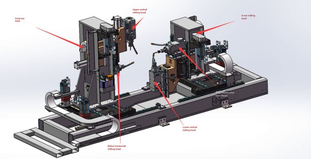
The four-axis standing milling position consists of two groups of milling heads: the front milling part and the back milling part. The front milling head is partially configured with a vertical milling head and a front horizontal milling head, which can complete element processing on the top and inner surface of the mold. The rear milling head is partially configured with a rear horizontal milling head and a lower vertical milling head, which can complete the element processing on the rear side and below the mold. In order to maximize production efficiency, two milling heads can be chosen to simultaneously process (upper vertical + lower vertical) according to the conditions of processing elements on the four sides of the mold. Up vertical + back horizontal; Lower vertical + pre-horizontal).
The drainage hole on the mold is generally processed according to the length of the mold and the specific requirements of the process. When multiple drainage holes need to be processed, the mold is handled sequentially by a mechanical hand.
The milling main axis of the four-axis milling machine is manually changed, so different specifications of machining tools need to be configured according to different machining processes.
L The second discharging platform : the processed profile is discharged by the second discharging platform ;
L Traction Manipulator: This part is equipped with two traction manipulators 3 # and 4 #。 4 # The mechanical hand adds an auxiliary mobile tightening device, which can adjust before and after moving to adapt to the changes in the tightening position of different types of materials.The auxiliary clamping device is suitable for secondary traction of the profile when the processed profile is larger than 3.2 meters.
This production line needs to be equipped with a separate CNC three-axis end surface mill during machining of the two ends of the middle mandrel type. When finished processing and labeled profiles on the production line, the barcode gun of the end surface mill scans the label content, and the numerical end surface mill automatically retrieves the stored profiles milling parameters for end surface milling.
The production line is automatic production mode, multiple stations can be processed at the same time, when the length range is in the range of 360 mm ~ 3200 mm, the processing of each station does not interfere with each other; When the processing length range is in the range of 3200mm-5000mm, due to the processing space of each station, in order to avoid mutual interference, the sequence of processing is required between each station, and the production efficiency may be reduced. Because the milling drainage hole speed is relatively slow, and the number of drainage holes is generally large, the workplaces are arranged to the last. When the milling workplaces have processed types, the front workplaces can not stop processing.
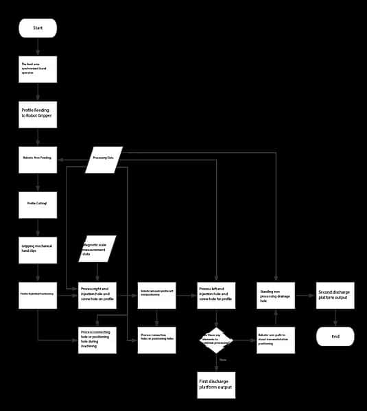
Dxplaination of the production line process
All processing data, aperture information, etc. of this production line must be provided by the door and window design software. The door and window design software generates a processing file for all the pore information that needs to be processed, and transmits it to the production line through the relevant transmission medium (USB flash drive or network), and the equipment processes in a sequential manner according to the processing data.
This equipment is standardly equipped with one operator, the loading area is manually loaded, and multiple types can be stored as a buffer zone, and the first and second loading tables can also store multiple types as buffers at the same time, so that the operator can complete the loading and loading between the loading zone and the loading areas.
Equipment machining parameters
Profile section width: 125 mm
Profile section height: 150 mm
Processing length range: 360-5000 mm
Machining length accuracy: ± 0.1 mm / 1000mm
Cutting angle accuracy: ± 5 ′
Distance between connecting holes or laser scribing for middle screws: min 400mm
Frame fixed hole spacing: min 280mm
Machinable structural elements
( 1 ) 45 ° cut at both ends of frame fan , 90 ° cut at both ends of center stile
( 2 ) Adhesive injection holes at both ends of frame slats
( 3 ) Corner bolt holes or pin holes at both ends of frame sash stiles
( 4 ) Fan drain holes , frame and mullion drain holes ( open drain , concealed drain , external open drain )
( 5 ) Center stud mounting screw hole or center stud marking line
( 6 ) Frame fixing hole
( 7 ) Fan milling sharp corner , guard corner , vent hole ( air pressure balance hole or isobaric hole )
( 8 ) Fan handle hole and lock body hole
( 9 ) Box Sliding Support Milling Rib
( 10 ) Hinge mounting hole
Device-related data
l Power supply : three-phase four-wire 380V 50Hz
l Drilling or milling spindle speed : max 9000r / min
l Drilling or milling spindle power : 3kW
l Cutting spindle power : 3kW
l Cutting spindle speed : 2860r / min
l Atmospheric pressure : 0.5–0.8MPa
l Gas consumption : 240L / min
l Total power : about 102kW
l Total weight : about 17 tons
l Dimension : 30.5 × 3.5 × 2.3m
Configuration instructions
U Motion Control System : Huichuan ( Servo , Motion Controller , Frequency Converter )
U Stepping System : XINJIE ( Stepping Motor , Stepping Driver , PLC )
U Pneumatic components : AIRTEC
U Milling , Cutting Spindle : Redworth
U Precision Reducer : DBS
U High Flexible Wire Cable : Shanghai Yichu
Low-voltage electrical components : Schneider , Omron , Honeywell
inverter : Delta
Sensor : Omron , Panasonic
linear guide : shangyin / yadeke
Ball Screws : TBI
Gears , Rack : YYC
Lubrication System : Proton
chain system : Huasite
Integrated intelligent production line capacity analysis for aluminum doors and windows
| Intelligent production line equipment operator | 1 person (general employment) |
| Average processing time | ≤20S / branch ( according to the different engineering and home decoration processing technology , the average processing time has increased or decreased ) |
| Productivity | According to 10 working hours per day, 10 x 60 x 60 ÷ 20 = 1800 |
| Number of windows completed per day | 1800 ÷ 10 = 180 |
| Complete the square numbers every day | According to 1.5×1.5 standard window calculation: 180 x 1.5×1.5 = 405 m2 |